Knock Sensor Testing
17th October 2012
I've always had an interest in knock sensing and or a couple of years I worked as senior electronics designer for a company that designs and manufactures piezo-electric accelerometers and
associated equipment, a knock sensor is just a piezo-electric sensor. I wouldn't describe myself as an expert but between myself and my colleagues we got by :-).
When I first decided to add a knock sensor to my motorbike I went into our assembly area and made myself one, after giving it some thought I decided that as I was going to publish the design I would use a sensor that could be sourced cheaply from any half decent vehicle breaker. The sensors I bought are Bosch part number 0261231121 and are from a Volvo 850 of some sort. There are two sensors wired into one connector, I will only be using one and so I will have a spare. These sensors seem to be advertised on eBay all the time, I paid around Ł10 for them.
I spoke to a chap at Bosch UK who was unable to provide me with a datasheet for that particular part but who explained that the sensors were much the same except for mountings and wiring. I did obtain a datasheet for a 0261231006 sensor from the web which defines all the required parameters and at the time I was fortunate enough to have access to all the equipment required to test a knock sensor so I could easily verify that the information was correct.
Testing
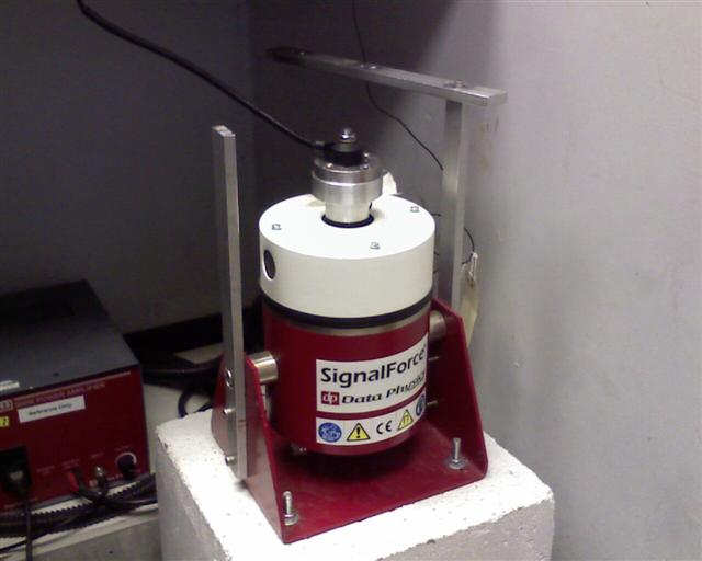
It is extremely important to mount the sensor to a flat and very rigid surface because surface irregularities or flex in the mounting will
cause unwanted resonances, the datasheet for the sensor will specify the required flatness. It is also important to make due regard to the orientation of the sensor,
these sensors are highly directional. In this instance I had to machine an adapter stud to bolt the sensor directly to the shaker table because my first tests with several different
adapters bolted together adapter were very disappointing. When mounting a sensor a smear of grease on the contact face can improve
the performance but this wasn't necessary in this case. There is also a special glue that we use that 'fills in the gaps", this might help
if the sensor was mounted to a non-machined location on an engine (such as an existing boss).
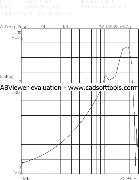
The sensor output was fed directly into the analyser (high impedance) to avoid loading the sensor andtThe analyser was set up to perform a frequency sweep at 1g between 1kHz and 25kHz. The result is shown below:
The sensor output was fed directly into the analyser (high impedance) to avoid loading the sensor andtThe analyser was set up to perform a frequency sweep at 1g between 1kHz and 25kHz. The result is shown below:
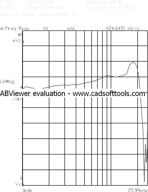
The result is as expected, the sensor response is relatively linear over the 3kHz to 15kHz range. The output voltage is very close to the 26mV/g at 5kHz quoted, this is quite pleasing
because the datasheet quotes a large tolerance on this. Both sensors were very similar although they would, obviously, be expected to be from the same batch. It should be noted that the
resonant peak seen at just below 25kHz is the first resonant peak, there may be others of a higher magnitude further up the frequency range which is why correct filtering of the signal is
very important.
Jaycar Interface
I don't have any intention of using this interface on my system but I've seen a few comments about it around the web so I thought I'd
pick one up and analyse it. I'm not going to publish the circuitry because it is copyright, its also so cheap that you'd have to be extremely
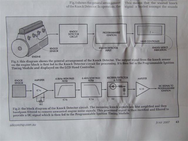
tight to begrudge paying the money. I will publish the block diagram because I'm too lazy to draw it out and because its fairly standard stuff.
I have to stress that the Jaycar circuit is not a knock detector as such, it is a signal conditioning interface for a knock sensor. The board is designed as an add on for their digital ignition kit, it amplifies the signal, filters it and converts it to a DC level. The ignition kit implements a very crude windowing technique followed by a variable threshold, this is necessary to pull the knock signal out of the background noise.
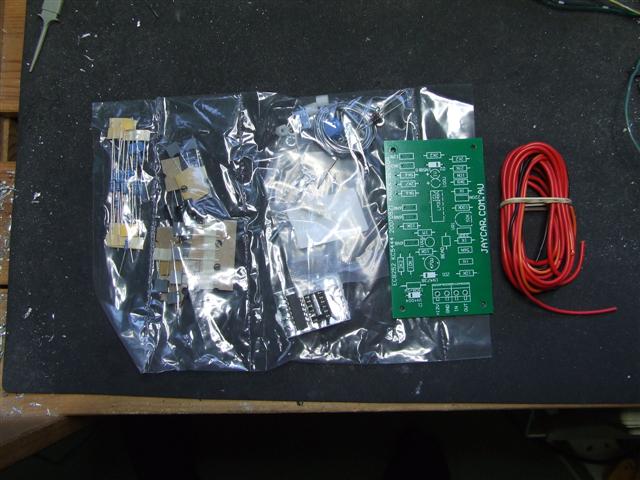
Here is what the kit looks like:
I have to stress that the Jaycar circuit is not a knock detector as such, it is a signal conditioning interface for a knock sensor. The board is designed as an add on for their digital ignition kit, it amplifies the signal, filters it and converts it to a DC level. The ignition kit implements a very crude windowing technique followed by a variable threshold, this is necessary to pull the knock signal out of the background noise.
Here is what the kit looks like:
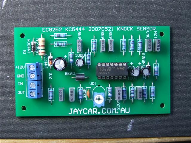
and the kit assembled:
First Impressions
The kit has the usual Jaycar flaws, the PCB layout looks like someone's college project and the voltage regulation is nowhere near
adequate for an automotive environment. PCB layout is critical to getting satisfactory EMC performance, theres a link to a Ford document in
my links page that explains good practice for PCB design.
The voltage regulator should be a proper automotive type or have a good deal of external protection. This circuit uses a zener diode
circuit so the vast majority of noise present on an automotive supply is going to pass straight through. It is also inadequate against load dump
conditions. There is also a lack of high frequency decoupling, easily fixed by adding a few 100nf caps across the supply and the op-amp.
These flaws would probably not be noticed by most people and hopefully your ECU or processing circuitry should have sufficient protection
to stop any noise problems being propagated. Other electronic devices should dissipate a load dump.
A ground connection for each signal would be a nice improvement and would allow the use of ferrules.
A ground connection for each signal would be a nice improvement and would allow the use of ferrules.
The circuit
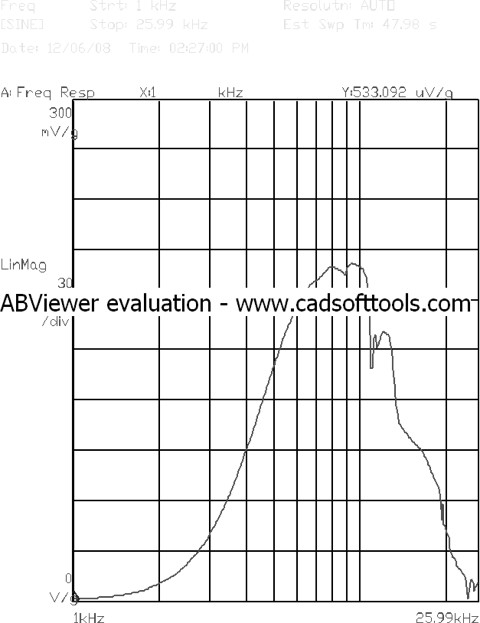
Starting at the input, the input impedance is very low, Jaycar use a 10K load resistance which is intended to improve the signal to noise ratio.
I think that this is a mistake, loading the sensor that highly reduces the input signal to the op-amp considerably and they do not use a low-noise op-amp.
The plot below shows the effect of this, the sensor is connected to just a 10K resistor and the analyser input. The resistor combines with the sensor itself
to become a high-pass filter and the input at 5kHz is reduced to around 7.5mV/g. I would use something like 100K
and turn down the sensitivity of the amplifier but maybe I'm just a bit fussy.
The filter stage is a 2nd order high pass filter followed by a 2nd order low pass filter. These combine to make a band pass filter that passes through just the
frequencies that we are interested in. A point to note here is that the two filters overlap to some extent and the knock signal is attenuated and then amplified
at each stage. The output from the filters is shown in the plot below, the sensitivity potentiometer has been set at approx mid-travel.
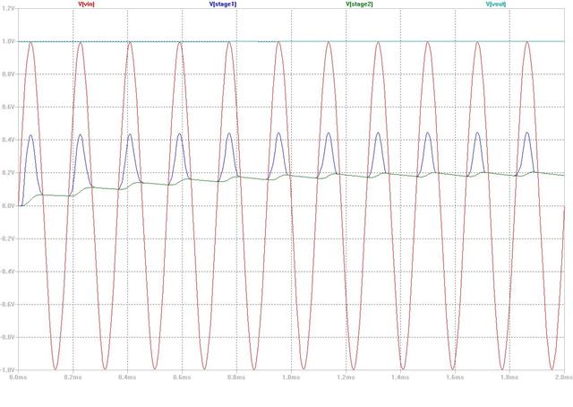
I don't have any plots of the rectifier and final amplification, it may be possible to set the analyser
up to record this but I didn't have the time or inclination, I did create a PSPICE simulation and that is shown below. The integration time is the critical parameter here,
it has to be long enough for the processing circuitry to detect knock but not too long such that it attenuates the signal and reduces the signal to noise ratio.
If you're not using the Jaycar ignition you might need to tweak the values a little.
Conclusion
In a knock sensor application we are looking for a signal at around 5-7kHz, the response of the filter is pretty good. Its a very
simple and cheap kit and the best thing about kits is that they make a great starting point - build it, play with it and improve it.
I mentioned earlier that I shan't be using the circuit, this is because I will be looking for more than just the knock signal. I will
be using a simple interface with a 4th order low pass filter and then processing the signal digitally. I have a tendancy to flit from one project to other so
don't expect anything very soon!
Knock Signal Analysis
The knock window
Knock occurs around the time that the cylinder is around its peak pressure on the combustion stroke. Various sources give different periods
for the knock window, a TI datasheet quotes 10degs ATDC to 70degs ATDC giving a knock window of 60degs.
A knock detector should be 'listening' only during the knock window. Because the input signal is integrated we need the knock sensor to be 'turned off' outside the window to avoid background noise being summed into the knock signal. The time period of the window will obviously reduce with increasing RPM. At 2000rpm a 60 degree window will last for 5mS and at 6000rpm the duration will be around 1.6ms.
If we have a knock signal at 7.5kHz and a window of 60degrees then the maximum number of cycles that we could measure would be 12. A number of low quality knock detectors have no sampling window or use a fixed duration window, these detectors will have a very poor signal to noise ratio. Its also worth noting that sampling on the combustion stroke only will avoid the detection of valve train noise, this would require multiple sensors on a multi-cylinder engine.
The knock frequency can be approximated using a simple formula:
900/(Pi * r) where r = the radius of the bore.
Given a bore of 76mm the knock frequency will be 7540Hz.
If we want to analyse the signal digitally then we need to chose the sampling frequency of the A to D converter very carefully. The Nyquist theory tells us that we can replicate the signal frequency at a sample rate of twice the input frequency but to replicate the signal amplitude we need to sample at something like ten times the rate. We therefore need a minimum sampling rate of at least 70KHz, the use of a PC soundcard is therefore not advisable.
A knock detector should be 'listening' only during the knock window. Because the input signal is integrated we need the knock sensor to be 'turned off' outside the window to avoid background noise being summed into the knock signal. The time period of the window will obviously reduce with increasing RPM. At 2000rpm a 60 degree window will last for 5mS and at 6000rpm the duration will be around 1.6ms.
If we have a knock signal at 7.5kHz and a window of 60degrees then the maximum number of cycles that we could measure would be 12. A number of low quality knock detectors have no sampling window or use a fixed duration window, these detectors will have a very poor signal to noise ratio. Its also worth noting that sampling on the combustion stroke only will avoid the detection of valve train noise, this would require multiple sensors on a multi-cylinder engine.
Sampling Rates
The knock frequency can be approximated using a simple formula:
900/(Pi * r) where r = the radius of the bore.
Given a bore of 76mm the knock frequency will be 7540Hz.
If we want to analyse the signal digitally then we need to chose the sampling frequency of the A to D converter very carefully. The Nyquist theory tells us that we can replicate the signal frequency at a sample rate of twice the input frequency but to replicate the signal amplitude we need to sample at something like ten times the rate. We therefore need a minimum sampling rate of at least 70KHz, the use of a PC soundcard is therefore not advisable.
Further Reading
| RhinoPower Home |